
7 Tips for Choosing Wheel Carrier Casting?
Choosing the right Wheel Carrier Casting is not a simple price comparison. This component supports wheel alignment, braking forces, suspension movement, and repeated road impacts. A poor decision may reveal itself through porosity, distortion, cracking, or premature wear. These problems often begin before machining.
Casting engineer and author John Campbell states, “The filling system should be designed to fill the casting with liquid metal without entraining air.” This principle remains highly relevant. Buyers should examine the alloy, casting method, mold design, heat treatment, and inspection records. A reliable supplier should explain how it controls shrinkage, inclusions, dimensional variation, and surface defects. Ask for material certificates and measurable process data. Photographs alone are not enough.
The best choice also depends on the vehicle platform and operating environment. Consider load direction, wall thickness, corrosion exposure, machining allowances, and fatigue requirements. A casting that performs well on a light passenger vehicle may fail under commercial-duty conditions. Small details matter. For example, a sharp internal corner can concentrate stress, while uneven cooling can alter critical dimensions.
Experience teaches another uncomfortable lesson: a clean-looking casting is not automatically a safe casting. Some defects remain hidden beneath the surface. My own evaluation framework would still be incomplete without production sampling and independent testing. That is where many purchasing decisions become too optimistic. These seven tips will help compare suppliers, verify technical claims, and select Wheel Carrier Casting with stronger evidence, not attractive assumptions.
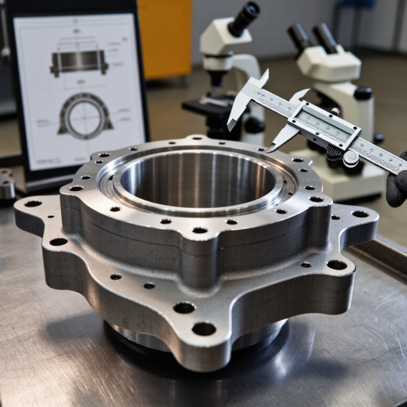
Define Wheel-Carrier Loads with 2–3 g Shock and Fatigue Requirements
7 Tips for Choosing Wheel Carrier Casting
Define Wheel-Carrier Loads with 2–3 g Shock and Fatigue Requirements
A wheel carrier casting should begin with measured loads, not a convenient safety margin. A 2–3 g shock event means the supported mass may experience two or three times gravity. Convert that acceleration into forces for braking, cornering, vertical impact, and combined events. Include wheel mass, hub mass, and fastener preload. Small details matter. A curb strike can create a sharp load spike within milliseconds.
Tip 1: Separate peak shock loads from repeated fatigue loads. The casting may survive one severe impact but crack after thousands of smaller cycles. Define cycle counts, load ratios, and stress direction before selecting an alloy or wall thickness. Tip 2: Check load paths around bearing seats, bolt holes, and suspension arms. These areas often carry concentrated stress. Use finite element analysis, then compare it with physical fatigue testing. Simulation alone can miss casting porosity or machining marks.
Tip 3: Specify the 2–3 g requirement with test conditions. State the acceleration direction, pulse duration, mounting position, and temperature. A 3 g vertical pulse is not equivalent to a 3 g lateral pulse. Tip 4: Inspect prototype sections for shrinkage defects and uneven material. I have found that a visually strong casting can still fail near a sharp transition. That result deserves review, not excuses. Add generous fillets, controlled section changes, and realistic manufacturing tolerances. The best choice balances strength, fatigue life, casting quality, and repeatable inspection.
7 Tips for Choosing Wheel Carrier Casting? - Define Wheel-Carrier Loads with 2–3 g Shock and Fatigue Requirements
Engineering screening guide for selecting a cast wheel carrier concept. Values are representative design targets and must be confirmed using the vehicle mass, suspension geometry, tire loading, road-load data, and applicable validation standards.
| Tip | Design Dimension | Recommended Screening Data | Why It Matters | Suggested Verification |
|---|---|---|---|---|
| 1 | Define the 2–3 g shock load case | Vertical shock acceleration: 2.0–3.0 g Equivalent acceleration: 19.6–29.4 m/s² Apply to the supported wheel-end mass and include simultaneous lateral and longitudinal load components where required. | A wheel carrier experiences high transient forces during pothole impacts, curb strikes, and severe bump events. A clear acceleration basis prevents underestimating bearing, flange, and knuckle loads. | Perform multibody load extraction followed by nonlinear finite-element analysis. Check plastic strain, local contact pressure, bolt-seat behavior, and permanent deformation after the shock event. |
| 2 | Convert vehicle loads into carrier interface loads | Evaluate three primary load directions: • Vertical: bump and rebound • Lateral: cornering and side impact • Longitudinal: braking and traction Include wheel offset, tire radius, control-arm locations, and brake torque in the load model. | The casting is governed by combined forces and moments rather than vertical force alone. Wheel offset and arm geometry can significantly amplify bending at the bearing bore and suspension lugs. | Create load cases at the wheel center, bearing center, brake interface, and suspension attachment points. Review force and moment equilibrium for every load case. |
| 3 | Set fatigue requirements before choosing the alloy and section size | Target durability: 1–3 million equivalent cycles for major road-load spectra, with separate high-load events for pothole and curb-impact cases. Use a fatigue safety factor of approximately 1.3–1.5 for preliminary assessment, subject to the project safety standard. | A casting that survives a single 3 g event may still fail under repeated load reversals. Fatigue performance depends strongly on stress concentration, porosity, surface finish, and local mean stress. | Use strain-life or stress-life analysis with cast-material fatigue data. Apply a spectrum-based durability calculation and conduct component fatigue testing at representative temperature and load ratios. |
| 4 | Match the casting process to the required integrity | Prefer a process capable of controlled wall thickness, stable dimensional accuracy, and low internal discontinuity levels in highly stressed regions. Typical structural wall thickness screening range: 4–8 mm, adjusted for alloy, geometry, and local loads. | Thin sections reduce mass but may increase filling risk, distortion, and sensitivity to porosity. Thick isolated sections can create shrinkage defects and residual stress. | Review filling and solidification simulation, section-thickness transitions, feeding paths, and process capability. Use radiographic, computed-tomography, or other approved internal-defect inspection where justified. |
| 5 | Control stress concentrations at attachment features | Use generous blended transitions and avoid abrupt thickness changes. Preliminary fillet-radius screening: 2–4 mm for highly loaded transitions, subject to tool access and casting capability. Keep fastener holes, bearing seats, and machined edges away from sharp load-path changes. | Fatigue cracks commonly initiate at lug roots, bearing-bore transitions, brake-mount bosses, and machined steps where local stress concentration is high. | Use local mesh refinement in finite-element analysis. Compare elastic peak stress, structural stress, and fatigue damage at each transition rather than relying only on global stress plots. |
| 6 | Specify dimensional and interface requirements | Control bearing-seat diameter, coaxiality, wheel-face runout, brake-mount position, and suspension-joint locations according to the vehicle tolerance stack. Define bearing-seat and fastener interfaces as critical-to-function features. | Dimensional error can cause bearing preload variation, brake runout, wheel alignment error, noise, vibration, and uneven tire wear even when structural strength is adequate. | Use a datum-based drawing and a coordinate-measuring inspection plan. Confirm bearing fit, runout, alignment, and assembled wheel-end performance after machining and coating. |
| 7 | Validate the complete wheel-end system | Recommended sequence: 1. Material and casting quality checks 2. Static proof loading 3. 2–3 g shock or impact simulation 4. Repeated fatigue loading 5. Corrosion and environmental exposure where applicable | Interaction among the carrier, bearing, hub, brake, fasteners, and suspension joints can change the actual load path. Component-only validation may miss assembly-level failures. | Test production-representative parts using production-representative machining, heat treatment, surface protection, fasteners, and assembly torque. Inspect for cracks, permanent deformation, loosened joints, and dimensional drift. |
Engineering note: The listed acceleration levels are screening inputs, not universal acceptance criteria. Final wheel-carrier requirements should be derived from the vehicle's gross mass, unsprung mass, tire and wheel assembly, suspension kinematics, road-load measurements, regulatory requirements, and project-specific safety factors.