
How to Choose Milling Cutters in 2026?

Choosing Milling Cutters in 2026 requires more than comparing catalog prices or counting flutes. Modern shops face harder alloys, tighter tolerances, smaller batches, and constant pressure to reduce cycle time. A cutter that performs well in aluminum may fail quickly in hardened steel. The details matter.

Professor Yusuf Altintas, a leading machining researcher, emphasizes, “Machining must be understood as an integrated system.” This principle should guide every cutter decision. Machine rigidity, spindle power, holder runout, workholding, coolant delivery, and programming all influence results. A premium cutter cannot correct a weak setup. Sometimes, the cheapest tool produces the highest cost per part.

This guide examines carbide grades, flute geometry, helix angles, coatings, corner designs, and application-specific tool choices. It also considers tool life, chip evacuation, surface finish, and predictable wear. For example, a five-flute end mill may improve productivity, but only when the machine can maintain suitable feed rates. In a flexible setup, fewer flutes may evacuate chips more safely.

Real production evidence should lead the decision. Record cutting speed, feed per tooth, radial engagement, axial depth, tool life, and scrap rates. Then compare the results. Not every recommendation will suit every workshop. That is an uncomfortable truth. Trial cuts remain valuable, especially when material certificates, machine condition, or operator habits vary. The best Milling Cutters strategy is practical, measurable, and open to revision.
How to Choose Milling Cutters in 2026?

Milling Cutter Basics: Types, Geometry, and Cutting Functions

How to Choose Milling Cutters in 2026?

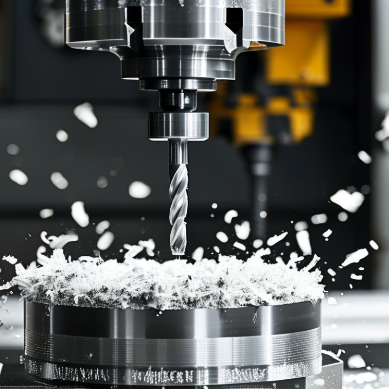
Milling cutters remove material through rotating teeth, but their geometry controls the result. End mills suit slots, profiles, and pockets. Face mills create broad, flat surfaces efficiently. Ball-nose cutters handle curved forms, especially in die and mold work. Chamfer mills prepare edges and remove sharp corners.

Look closely at the cutting angles. A positive rake angle reduces cutting force and helps softer metals flow away. A stronger edge often needs a smaller rake angle for hardened materials. Helix angle also matters. Higher helixes usually improve chip evacuation, while lower helixes can support difficult, interrupted cuts. Tooth count changes everything. Fewer flutes leave more space for chips. More flutes can improve finish when feed and coolant are controlled.

Coating and substrate should match the workpiece, not simply the machine’s maximum speed. For aluminum, polished flutes and generous chip space usually prevent built-up edges. For stainless steel, a sharp but durable edge helps avoid rubbing. I check spindle power, tool overhang, workholding, and coolant access before choosing diameter. Small details matter. A cutter that looks ideal on a chart may chatter in a flexible setup. In practice, I record sound, surface finish, chip shape, and tool wear after each trial. My first selection is rarely perfect. Adjusting feed rate may solve a problem that seems to require a different cutter, though not always.

How to Choose Milling Cutters in 2026?

Milling Cutter Basics: Types, Geometry, and Cutting Functions

Helix angle affects chip evacuation, cutting smoothness, axial force, and vibration. Low-helix cutters are commonly used for brittle materials and interrupted cuts, while high-helix cutters generally provide smoother cutting and improved chip removal in ductile materials such as aluminum. The values shown are typical industry ranges represented by commonly used nominal geometries; the correct cutter still depends on workpiece material, machine rigidity, depth of cut, and coolant conditions.

Match the Cutter to the Material and Machining Operation

How to Choose Milling Cutters in 2026?

Match the cutter to the material and machining operation, not merely the machine’s spindle speed. For aluminum, use polished carbide flutes with generous chip space. They reduce built-up edge during high-feed slotting. Steel usually needs tougher carbide grades, moderate rake, and controlled coolant. Stainless steel demands sharp edges and interrupted-cut stability. A sharp cutter is not always the safest cutter.

For hardened steel, consider a small-diameter solid carbide tool with strong edge support. Ceramic can work in stable, high-temperature cuts, but it dislikes sudden impact. The operation matters just as much as the workpiece. Roughing needs high core strength and chip evacuation. Finishing needs runout control, low cutting forces, and predictable edge geometry. In my shop experience, excessive tool length causes more failures than poor grade selection. Shorter is often better.

Material availability also deserves attention. The U.S. Geological Survey’s Mineral Commodity Summaries 2024 reported approximately 78,000 metric tons of global tungsten mine production for 2023. Tungsten carbide selection should therefore consider tool life, regrinding, and actual removal rates, not only purchase price. ISO 513 provides a useful framework for comparing tool-material groups, but it cannot replace a cutting test. Start with the maker’s recommended speed range, then reduce it when chatter, heat, or burrs appear. I still occasionally choose an aggressive feed first. That mistake is expensive. Record spindle load, edge wear, and surface finish after every trial. Rescue the process with evidence, not instinct.

Choose Cutter Diameter, Tooth Count, and Helix Angle

How to Choose Milling Cutters in 2026?

Choose Cutter Diameter, Tooth Count, and Helix Angle

Cutter diameter should match the machine, workpiece, and cutting depth. A larger cutter spreads heat across more teeth and often improves stability. However, it needs greater spindle power. In a small machining center, an oversized cutter may cause vibration or overload. Measure the available clearance carefully. Leave room for chips and tool movement.

Tooth count controls chip space and feed potential. Fewer teeth provide larger gullets for aluminum and other soft materials. They also help remove long chips from deep pockets. More teeth can support higher feed rates in steel, but only when chip evacuation remains reliable. I once assumed more teeth always meant faster cutting. That choice produced packed flutes and a poor surface.

Helix angle affects cutting smoothness, axial force, and chip direction. A higher helix usually cuts quietly and reduces impact, especially on thinner walls. Yet it can pull the workpiece upward if clamping is weak. Lower helix cutters may offer better control for hard materials or shallow shoulder work. Check the cutter maker’s speed, feed, and radial engagement data before testing. Start conservatively, listen for changes, and inspect the chips. Bright blue chips often indicate excessive heat, while thick, broken chips may show insufficient feed. Real results still depend on workholding, coolant delivery, machine rigidity, and tool condition. Temperature readings and wear marks tell a more reliable story than appearance alone.

Set Cutting Speed, Feed Rate, and Depth of Cut

How to Choose Milling Cutters in 2026?

Tool selection starts with cutting speed, feed rate, and depth of cut. Cutting speed depends on cutter diameter and spindle speed: Vc = πDN/1,000. For a 50 mm cutter running at 2,000 rpm, the speed is about 314 m/min. Check the cutter maker’s range, then reduce it for interrupted cuts, weak fixtures, or hard materials. The 2024 U.S. Cutting Tool Consumption report recorded monthly industry shipments frequently exceeding 200 million dollars, showing how costly poor process control can become.

Feed rate requires equal care. Calculate it from feed per tooth, tooth count, and rpm: Vf = fz × z × N. A four-tooth cutter using 0.06 mm per tooth at 2,000 rpm needs 480 mm/min. If the machine sounds sharp and produces long chips, increase feed gradually. If the tool rubs, reduce speed or increase feed slightly. Strange, but rubbing often creates more heat than cutting.

Depth of cut should match rigidity, tool diameter, and material removal goals. A 50 mm cutter may tolerate a 1–2 mm axial cut in finishing, while roughing may use a smaller radial engagement and deeper axial cut. ISO 3685 tool-life methods support controlled testing, but shop conditions rarely match laboratory tests. I still verify one change at a time. That habit prevents false confidence. Leave a small allowance for finishing, measure the wall, and record tool wear after each run.

How to Choose Milling Cutters in 2026? - Set Cutting Speed, Feed Rate, and Depth of Cut
Workpiece Material Recommended Cutter Typical Flute Count Starting Cutting Speed, Vc
(m/min)
Feed per Tooth, fz
(mm/tooth)
Axial Depth of Cut, ap Radial Width of Cut, ae Coolant or Lubrication Selection and Adjustment Notes
Aluminum alloys, such as 6061 and 7075 Polished solid-carbide end mill with a high helix angle 2–3 250–500 0.05–0.15 1.0–2.0 × cutter diameter for slotting;
up to 3.0 × diameter for adaptive roughing
0.10–0.50 × cutter diameter Air blast or minimum-quantity lubrication; flood coolant where suitable Use a polished flute and strong chip evacuation. Reduce speed or feed if built-up edge or chip welding occurs.
Free-machining brass and bronze Sharp solid-carbide or high-speed-steel end mill with a positive rake 2–4 150–300 0.04–0.12 0.5–1.5 × cutter diameter 0.15–0.50 × cutter diameter Dry machining or air blast is often effective Avoid excessive rubbing. Use a sharp edge and reduce radial engagement if chatter develops.
Low-carbon and mild steel Solid-carbide or carbide-indexable end mill with a variable helix 4–5 120–220 0.03–0.08 0.5–1.5 × cutter diameter 0.10–0.40 × cutter diameter Flood coolant or directed air, depending on machine and tooling Use a tougher edge for interrupted cuts. Lower cutting speed when scale, hard spots, or vibration is present.
Alloy steel, approximately 30–40 HRC Coated solid-carbide end mill with a variable pitch 4–5 80–160 0.02–0.06 0.3–1.0 × cutter diameter 0.05–0.30 × cutter diameter Flood coolant or high-pressure air Use stable tool holding and minimize runout. Reduce radial engagement before reducing feed per tooth.
Austenitic stainless steel, such as 304 and 316 Variable-helix solid-carbide end mill with a strong, sharp edge 4–5 60–120 0.02–0.06 0.3–1.0 × cutter diameter 0.05–0.25 × cutter diameter Continuous flood coolant or high-pressure coolant Do not dwell in the cut. Maintain sufficient chip thickness to prevent work hardening and rubbing.
Gray cast iron Carbide end mill with a wear-resistant edge 4–6 100–180 0.03–0.08 0.5–1.5 × cutter diameter 0.10–0.40 × cutter diameter Dry machining with strong air blast; coolant may be used if approved for the machine Protect the machine from abrasive dust. Reduce speed when flank wear or edge chipping increases.
Titanium alloys, such as Ti-6Al-4V Sharp, tough solid-carbide end mill with variable pitch and reduced radial engagement 4–5 30–60 0.015–0.04 0.2–0.8 × cutter diameter 0.05–0.15 × cutter diameter High-pressure flood coolant Maintain constant tool engagement and avoid heat buildup. Use a rigid setup and replace tools before excessive wear.
Nickel-based heat-resistant alloys Short, rigid solid-carbide or ceramic-compatible cutter selected for the machine 4–6 15–40 0.01–0.03 0.1–0.5 × cutter diameter 0.03–0.12 × cutter diameter High-pressure coolant where compatible with the tool Use low radial engagement and avoid dwell. These values require confirmation from the tool supplier and machine capability.
Hardened tool steel, approximately 45–55 HRC Aluminum-titanium-nitride-type coated carbide or equivalent hard-milling cutter 4–6 40–80 0.01–0.04 0.1–0.5 × cutter diameter 0.03–0.15 × cutter diameter Dry air blast or controlled coolant, according to tool guidance Use a rigid machine and short tool overhang. Reduce speed if heat, chipping, or excessive tool wear appears.
Core Calculations: Spindle speed, n = (1,000 × Vc) ÷ (π × D); Table feed, Vf = n × z × fz. Here, Vc is cutting speed in m/min, D is cutter diameter in mm, z is the number of flutes, and fz is feed per tooth in mm/tooth.
The values above are practical starting ranges for carbide milling and should be validated with the cutter geometry, workholding rigidity, machine power, tool diameter, material condition, and manufacturer's technical data. When increasing material removal rate, adjust radial engagement, axial depth, cutting speed, and feed together rather than changing only one parameter.

Compare Tool Materials, Coatings, Cost, and Tool Life

How to Choose Milling Cutters in 2026?

Tool material controls cutting speed, heat resistance, and replacement cost. Carbide suits most steel and aluminum operations. High-speed steel remains practical for low-speed machines and interrupted cuts. Ceramic handles extreme heat, but it dislikes vibration. CBN works well on hardened steel, while PCD performs best in abrasive non-ferrous materials. The USGS Mineral Commodity Summaries 2025 reported about 81,000 metric tons of global tungsten mine production in 2024. Supply concentration can influence carbide costs. Therefore, the cheapest cutter may create higher long-term risk.

Coatings also change tool life. A multilayer coating can reduce friction and protect the cutting edge. However, thicker is not always better. Aluminum may need a sharper, low-friction surface. Stainless steel needs stronger heat and wear protection. Compare cost per usable edge, not purchase price. ISO 8688 tool-life testing offers a useful structure for controlled comparisons. Record cutting speed, feed, radial engagement, and failure mode. In real workshops, tool-life results often vary. Machine rigidity is the uncomfortable variable.

Tips:

Run a short trial first. Use identical workpieces and coolant conditions. Measure edge wear under magnification. If one cutter lasts 20 minutes longer but costs twice as much, calculate the real cost per part. A 2024 manufacturing outlook from Deloitte also highlights data-based process control as a major competitiveness factor. Still, perfect data does not replace operator judgment. Check the chips. Listen to the cut. Then adjust carefully.

Article Source: