How to Design and Fabricate a Flex Circuit Board?
In the rapidly evolving electronics industry, the demand for flex circuit boards is on the rise. According to a report by the Research and Markets, the global flexible printed circuit board market is expected to grow at a CAGR of 9.5% from 2021 to 2026. This growth is driven by the increasing miniaturization of electronic devices and the need for lightweight solutions in various applications.
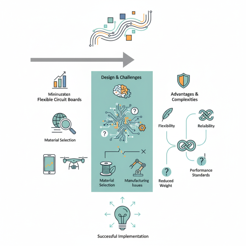
Industry expert Dr. Jane Thornton, a leading authority on flexible electronics, states, "Flex circuit boards are crucial for modern applications, allowing for innovative designs in tight spaces." The intricate design and fabrication processes of flex circuit boards present challenges. Designers must carefully consider material selection and manufacturing techniques. Mistakes in these areas can lead to performance issues in the final product.
Flex circuit boards offer significant advantages, such as flexibility and reduced weight, but these benefits come with complexities. Engineers often face difficulties in ensuring reliability while maintaining performance standards. Understanding these nuances is vital for successful implementation.
Understanding Flex Circuit Board Basics
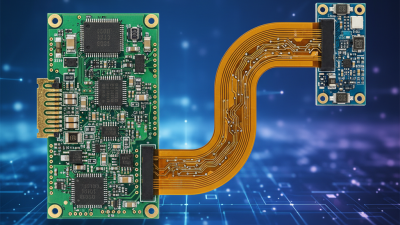
Flex circuit boards, also known as flexible printed circuits, are essential in modern electronics. They allow for complex designs in compact spaces. Understanding their structure is key to effective design. These circuits often consist of a polymer substrate. Common materials include polyimide and polyester. They can bend and twist without breaking.
Designing a flex circuit involves knowing its layers. A basic flex circuit includes a conductive layer, usually copper. This layer is bonded to the substrate. The layer's thickness and pattern are crucial for conductivity. The design must account for bends and folds. Miscalculations can lead to failure, causing frustration.
Fabricating these circuits requires precision. Techniques like etching and lamination are commonly used. Each step requires careful attention. Mistakes can compromise the circuit’s integrity. Testing is vital to ensure functionality. Often, it's a trial-and-error process. It's important to reflect on each choice. Revisions may be necessary to get results. Embracing flexibility in design can lead to innovative solutions.
Flex Circuit Board Material Usage
Material Selection for Flex Circuit Fabrication
When it comes to flex circuit fabrication, material selection is pivotal. Polyimide films are popular for their thermal stability and flexibility. According to a recent industry report, polyimide usage can improve circuit durability by up to 30%. This makes it an excellent choice for various applications, including consumer electronics and automotive components.
Copper is the typical conductor material, chosen for its excellent conductivity. However, its weight can be a concern. Alternative materials, such as aluminum, are gaining traction. Using aluminum can reduce weight by approximately 40%, but its conductivity is lower. Designers face challenges balancing weight and performance.
In some cases, adhesive choices can impact reliability. A poorly chosen adhesive may lead to delamination. Data indicates that over 25% of failures in flex circuits can be attributed to adhesive weaknesses. This highlights the need for careful material selection throughout the fabrication process. Balancing cost with performance can be tricky, as opting for cheaper materials may lead to long-term issues.
Design Considerations for Flex Circuit Layouts
Designing and fabricating a flex circuit board requires careful planning. Flex circuits can bend and twist, making them ideal for compact devices. However, not all designs will work seamlessly. Flexibility must be matched with the component layout. Sometimes, this balance is tricky.
When laying out a flex circuit, consider the materials. Polyimide is popular for its durability. But thinner materials might not always provide the needed support. Too many bends in the layout can lead to cracking. Avoid tight radii; they can compromise the circuit’s integrity. Test your design with simulated bending to catch potential issues early.
Another factor is trace width. If traces are too narrow, they may not handle current well. On the flip side, wider traces take more space and can limit layout options. Think about solder joint strength, especially for components subjected to movement. Every decision counts. It's essential to iterate on designs based on early prototypes. Each prototype teaches valuable lessons for future revisions.
Manufacturing Process Steps for Flex Circuits
Designing and fabricating a flex circuit board involves several key manufacturing process steps. Begin with material selection. The substrate is often polyimide or polyester. These materials provide flexibility and durability. Finely tune the thickness based on the application. A thicker substrate might enhance stability but could reduce flexibility.
Next, create a photolithographic mask. This mask defines the circuit pattern. Apply a photosensitive film onto the substrate and expose it to UV light. The exposed areas harden, forming a protective layer. Remove the unexposed sections. This step demands precision. Any mistake could lead to circuit failures later.
After etching the copper, the flex circuit must be developed. Remove the unwanted copper to reveal the conductive paths. Ensure the edges are smooth and well-defined. Incomplete etching might cause short circuits. Lastly, apply protective coatings. Choose a finish that suits the environment. Testing the circuit before final assembly is crucial. Verify functionality, as errors at this stage can be costly.
Testing and Quality Assurance for Flex Circuit Boards
Testing and quality assurance for flexible circuit boards is crucial. The manufacturing process demands precise measurements and checks. Each board must undergo rigorous testing to ensure functionality. This includes visual inspections and electrical tests. Often, minor defects can be overlooked. These can lead to significant issues later. Regular audits of the testing procedures help catch flaws early.
It is essential to create a robust quality assurance plan. Implementing standard operating procedures is a good start. However, not all teams follow them consistently. This inconsistency may impact the final product. Providing additional training can mitigate risks. Having a designated team to oversee quality can also be helpful. They can identify patterns of defects over time.
Real-world testing might reveal unexpected challenges. For example, bending tests should simulate actual use conditions. Sometimes, boards fail unexpectedly during these tests. It can be discouraging but allows for improvements. Ensuring that every step of the process meets rigorous standards is vital. Continuous reflections on the testing approach lead to innovations in the process.