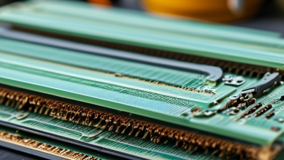
What Are the Top Benefits of Flex PCBs?
Flex PCBs are changing how engineers approach compact electronic products. Unlike rigid boards, they can bend, fold, and fit into narrow spaces. This matters in smartwatches, medical instruments, cameras, automotive displays, and wearable sensors. A flex PCB may follow a curved housing like a thin ribbon, reducing the need for bulky wire bundles and extra connectors.
Joe Fjelstad, a recognized flexible-electronics expert, expresses the design principle clearly: “Design for flexibility, rather than simply adding flexibility.” His point deserves attention. Flex PCBs are not automatically better in every application. They require controlled bend radii, suitable copper structures, reliable coverlay materials, and careful assembly processes. Poor routing can create stress at the same corner repeatedly. That small mistake may become a field failure.
The strongest benefits appear when flexibility solves a real mechanical problem. Flex PCBs can reduce product weight, save internal space, and simplify three-dimensional connections. Fewer connectors may also mean fewer contact points that can loosen or corrode. In dynamic applications, properly designed circuits can withstand repeated movement more effectively than traditional wiring. They can also improve airflow and support thinner product profiles.
Still, the technology has trade-offs. Material selection, impedance control, inspection, and production yield can increase costs. Designers sometimes focus on the bend and overlook heat, vibration, or repair access. That is a reasonable concern. This guide examines the top benefits of flex PCBs while considering the practical limits that influence their reliability, manufacturability, and long-term value.

What Are Flex PCBs and How Do They Work?
What Are the Top Benefits of Flex PCBs?
What Are Flex PCBs and How Do They Work?
Flex PCBs are circuit boards made with thin, bendable materials instead of rigid fiberglass. Their conductive copper layers sit on flexible films, commonly supported by protective cover layers. This structure allows the circuit to fold, twist, or fit around tight spaces. In a wearable device, for example, a flex PCB can run from a small sensor to a curved control module. It replaces several wires and connectors. That can reduce weight, assembly time, and failure points.
Flex PCBs work like standard circuit boards, but their mechanical design is different. Copper traces carry electrical signals across the flexible substrate. Stiffened areas can support connectors or components during installation. Engineers must control bend radius, copper thickness, and repeated movement. A sharp fold may damage the traces. That detail is easy to underestimate. In practice, careful testing is essential because laboratory movement may not match real handling.
Tips: Define the bending area early. Keep components away from repeated flex zones. Inspect copper traces after assembly, especially near corners and connector transitions. A reliable design also considers heat, vibration, moisture, and repair access. Flex circuits offer impressive freedom, but they are not automatically stronger than rigid boards. Their value comes from using flexibility where the product genuinely needs it.
How Do Flex PCBs Reduce Space and Product Weight?
Flex PCBs are valuable when products must become smaller, lighter, and easier to assemble. Their thin, bendable structure fits around corners and through narrow spaces. Unlike rigid boards, they do not need separate cables for every moving connection. A circuit can fold, curve, or sit against a housing wall. This flexibility releases valuable internal volume. In compact sensors, medical devices, and handheld equipment, every millimeter matters.
A flex circuit can replace several wires, connectors, and small adapter boards. That reduction simplifies the internal layout and removes extra mechanical parts. Fewer connections can also reduce assembly steps and potential failure points. The weight savings may seem modest at first. However, removing multiple cables and connector housings can noticeably improve portability. Engineers can also use the recovered space for batteries, shielding, or stronger structural parts. Design reviews should measure these gains, not assume them.
Flex PCBs still require careful engineering. The bend radius, copper thickness, and reinforcement must match the product’s movement pattern. Repeated sharp bending can create fatigue, even when the first prototypes perform well. Assembly teams also need clear handling and inspection procedures. A thinner circuit is not automatically a better circuit. Experienced designers balance space savings against material cost, testing requirements, and long-term reliability. Sometimes, a slightly thicker flex design delivers a more dependable product.
Why Do Flex PCBs Improve Design and Assembly Flexibility?
Flex PCBs improve design and assembly flexibility by replacing rigid wiring with a shaped interconnect. Their thin polyimide structure can fold around corners, fit beneath batteries, and connect moving sections without bulky cable bundles. Designers gain space, but not unlimited freedom. A bend still needs a controlled radius, and repeated motion requires a tested flex zone. In practical layouts, I reserve stiffeners near connectors and keep copper transitions away from sharp folds. Small choices like these help prevent cracking during assembly and service.
Assembly also becomes more predictable when the circuit follows the product’s natural shape. Fewer connectors mean fewer mating errors, less wiring, and a cleaner path for inspection. Flex circuits can arrive with defined folds, allowing technicians to place them into narrow housings with less rework. I have found that early 3D checks reveal problems that flat drawings hide, especially near screws, hinges, and heat sources. However, folding too early can stress solder joints. Temporary supports and a clear insertion sequence are often necessary.
Good engineering includes limits. Designers should confirm bend radius, layer symmetry, copper type, adhesive behavior, and impedance requirements with the fabricator. They should also test the finished assembly under vibration and repeated flexing. One overlooked detail can erase the expected benefit. Flex PCBs are not automatically easier to build; unclear tolerances can make them harder to inspect. Design reviews, sample builds, and honest failure analysis remain essential.
How Do Flex PCBs Enhance Durability and Reliability?
Flex PCBs improve durability by replacing rigid boards and wired joints with a continuous, bendable circuit. In equipment with moving lids, hinges, or tight corners, this matters daily. A well-designed flex layer follows motion instead of resisting it. Fewer connectors also mean fewer contact points that can loosen, corrode, or fail under vibration. I have seen small connector faults cause difficult intermittent failures. Flex construction can remove that weak link. Not every flex circuit is automatically rugged.
Reliability depends on bend radius, copper type, layer stack, and reinforcement around connectors. Repeated bending beyond the specified radius can crack copper traces, even when insulation looks perfect. Dynamic applications need controlled flex zones and smooth transitions. Static bends still require careful forming. Coverlay protects traces from moisture, abrasion, and handling damage. Stiffeners support soldered components and reduce stress near termination areas. During qualification, engineers should combine bend-cycle testing with thermal cycling, vibration, and electrical continuity checks. A circuit may pass visual inspection and still fail after thousands of movements. Testing should reflect real product motion, not ideal laboratory conditions.
Flex PCBs also reduce assembly weight and save space, which can lower mechanical strain. Their compact routing helps prevent sharp wire paths and accidental pinching. However, designers sometimes optimize thickness too aggressively. That choice can weaken handling durability and repairability. Material tolerances matter. So do operator technique and assembly pressure. A durable circuit is less useful if technicians must fold it sharply during replacement.
What Are the Top Benefits of Flex PCBs? - How Do Flex PCBs Enhance Durability and Reliability?
| Benefit or Reliability Factor | How Flex PCBs Improve Performance | Durability and Reliability Impact | Typical Design Considerations | Best-Fit Applications |
|---|---|---|---|---|
| Reduced Interconnects | Flex circuits can integrate wiring, connectors, and multiple rigid-board connections into one continuous circuit. | Fewer solder joints, cable interfaces, and mechanical connectors reduce potential points of electrical failure. | Use controlled routing, adequate bend areas, and appropriate strain relief at transitions. | Compact electronics, instrument panels, medical devices, and automotive control modules. |
| Resistance to Vibration and Shock | The lightweight circuit structure can absorb movement more effectively than a rigid board connected by several separate cables. | Lower mechanical stress on interconnects can help reduce intermittent faults caused by vibration, impact, or repeated movement. | Secure the flex section properly and avoid placing components or vias in high-flex zones. | Portable equipment, aerospace systems, industrial controls, and moving assemblies. |
| Dynamic Flexing Capability | Purpose-built flex constructions can repeatedly bend along a defined axis during product operation. | When the bend radius, copper type, layer count, and bend cycles are properly specified, the circuit can support repeated motion without relying on cable connectors. | Dynamic applications generally require a larger bend radius than static applications; a common starting guideline is at least 100 times the finished flex thickness, subject to material and construction validation. | Hinged devices, robotic equipment, printer mechanisms, sensors, and moving displays. |
| Improved Space Utilization | Thin flexible sections can fold, wrap, or conform to three-dimensional product geometry. | Shorter routing paths and fewer bulky cable bundles can reduce assembly interference and movement-related wear. | Maintain the specified bend radius and provide clearance from sharp edges, screws, and moving parts. | Wearables, cameras, handheld products, consumer electronics, and compact medical equipment. |
| Lower Weight | Flex circuits can replace heavier wire harnesses, connectors, and mechanical supports in suitable designs. | Reduced mass lowers the inertial load on moving assemblies and may reduce stress during shock or vibration events. | Weight savings depend on layer count, copper thickness, stiffeners, shielding, and connector requirements. | Portable devices, drones, aerospace equipment, automotive interiors, and battery-powered products. |
| Stable Electrical Performance During Movement | A properly designed flex circuit maintains defined conductor spacing and routing while the product changes position. | Continuous traces can provide more consistent signal paths than loosely arranged wires that may move, rub, or disconnect. | High-speed designs may require controlled impedance, shielding, grounding, and bend-aware stack-up planning. | Display interfaces, cameras, communication modules, sensors, and data-acquisition systems. |
| Thermal and Environmental Adaptability | Polyimide-based flex constructions can operate across broad temperature ranges when the materials and bonding systems are correctly selected. | Suitable material selection helps the circuit withstand thermal cycling, humidity, and mechanical movement without premature delamination or cracking. | Validate the complete material system, including coverlay, adhesive, solder mask, stiffeners, and surface finish, for the intended environment. | Automotive, industrial, aerospace, medical, and high-temperature instrumentation. |
| Simplified Assembly | Integrated flex sections can reduce wire preparation, routing, and manual connector assembly steps. | Fewer assembly operations can reduce variation, handling damage, and installation errors. | Include tooling features, bend guides, insertion protection, and clear assembly instructions in the design. | High-volume electronics, automated equipment, compact modules, and products with limited assembly space. |
| Better Long-Term Connection Integrity | Eliminating unnecessary plug-and-socket interfaces reduces exposure to fretting, oxidation, contamination, and connector loosening. | Directly integrated interconnects can improve continuity over the product service life when mechanical stress is controlled. | Use appropriate contact finishes, strain relief, bend stiffeners, and qualification testing for the operating environment. | Products requiring high uptime, service equipment, transportation systems, and embedded electronics. |
Note: Actual durability and reliability depend on the flex-stack construction, materials, copper type, bend radius, operating temperature, assembly process, and qualification testing. Common bend-radius guidelines are starting points rather than universal requirements.
Which Applications Benefit Most from Flex PCB Technology?
Flex PCBs are especially valuable where space, movement, and weight matter. Wearable health monitors can place circuits inside thin bands or curved patches. Their bendable structure follows the body more comfortably than rigid boards. Small cameras, smart glasses, and portable instruments also benefit from fewer wires and compact routing. In practice, this can simplify assembly around hinges, corners, and narrow enclosures.
Medical equipment uses flex circuits in monitoring patches, hearing devices, and compact diagnostic tools. Designers can route signals through tight spaces while reducing connector points. That may improve reliability during repeated movement. Automotive displays, steering controls, and sensor modules face similar demands. Flex PCBs can fit behind curved panels and tolerate controlled vibration when properly designed. They are not automatically stronger, though.
Aerospace instruments and robotic joints benefit from reduced mass and flexible interconnections. In a robotic arm, a flex circuit may move through a joint without the bulk of several separate cables. Cameras and inspection equipment can use them where repeated folding is carefully controlled. The fit is rarely perfect on the first revision. Engineers must check bend radius, heat, materials, and assembly stress early. Poor routing can still cause cracks, signal loss, or costly redesigns. Surface protection also matters in humid, dusty, or chemically exposed environments.
Related Posts
-
What Are the Best China Flex PCBs for Global Buyers?
-
10 Best Flex PCB Boards You Should Consider for Your Next Project?
-
How to Choose the Right Flex PCBs Worldwide?
-
10 Best Rigid Flex PCB Options for Your Electronics Projects?
-
What Are the Best China Flex PCBs for Global Buyers?
-
How to Choose the Best Flexible PCB Board for Your Project?