
What Is a Flexible Circuit Board?
A flexible circuit board carries electrical pathways on a thin, bendable insulating film. Unlike a conventional rigid board, it can fold or curve to fit inside compact products. Common materials include polyimide, copper conductors, and a protective coverlay. Each layer has a practical job. The film supports the circuit, while the copper traces carry signals and power. In a camera module, for example, a narrow circuit can link a sensor to the main board through a tight space. Small, but useful.
That flexibility can reduce weight, simplify connections, and free space for other components. Yet “flexible” does not mean indestructible. A board designed for one gentle bend may fail if repeatedly folded, sharply creased, or pulled at its connector. Bend radius, copper type, layer count, and assembly conditions all affect reliability. These details are easy to underestimate. Flexible circuits also cost more than some rigid alternatives, so their benefits should match the product’s needs. A rigid-flex design combines flexible sections with rigid areas, but it is not the same as a fully flexible circuit. The distinction matters when comparing designs. This guide explains how flexible circuit boards are built, where they are used, and what to consider before selecting one. Real designs involve trade-offs, and the best choice depends on space, movement, durability, and budget.
What a Flexible Circuit Board Is
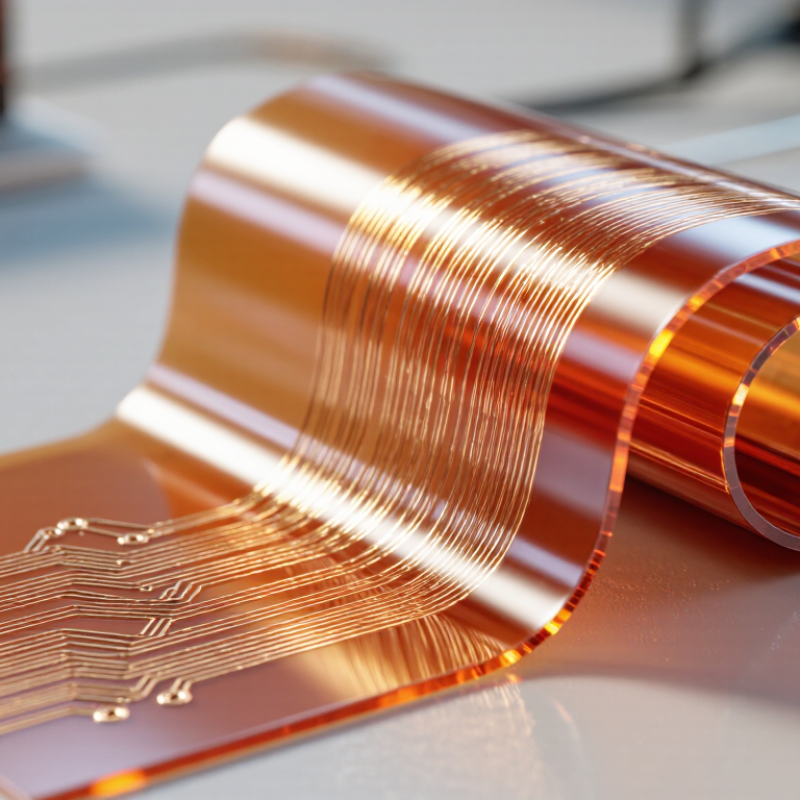
A flexible circuit board is an electronic circuit built on a thin, bendable insulating film rather than a rigid board. It commonly uses copper traces laminated to a polymer substrate, with a protective coverlay over the conductors. Polyimide is a widely used substrate because it tolerates heat and repeated handling. The finished circuit may have one or several conductive layers, depending on how many connections the device needs.
It bends. But not without limits. A flex circuit can follow a hinge, curve around a compact enclosure, or connect parts that move relative to each other. Its bend radius, copper thickness, and layer arrangement affect how safely it flexes. A sharp crease can damage the copper, even when the outer film looks intact. Designers therefore specify whether the circuit will bend once during installation or repeatedly during use. Those are different demands.
In practical assembly, connectors and soldered components usually need support because their weight can concentrate stress on the flexible section. Small examples include a camera module linked to a main board or a sensor tucked inside a narrow instrument. One detail that is easy to underestimate is the transition between rigid and flexible areas; poor strain relief can lead to cracking over time. Flex circuits save space, though they can require careful layout and handling. A neat drawing alone does not prove the bend will work.
| Dimension | Description | Practical Notes |
|---|---|---|
| Definition | A flexible circuit board, also called a flex circuit or FPC, is an electrical circuit built on a bendable insulating substrate. | It can be designed to fold or conform to a product’s shape, unlike a conventional rigid board. |
| Common substrate | Polyimide is widely used because it offers flexibility and can tolerate the heat involved in many electronics assembly processes. Polyester films are used in some applications. | Material choice depends on operating temperature, flexibility, cost, and assembly requirements. |
| Conductive layer | Copper foil forms the electrical traces. Flexible circuits may use rolled-annealed or electrodeposited copper. | Rolled-annealed copper is often selected for circuits that must withstand repeated bending. The appropriate copper type depends on the design and use. |
| Protective cover | A coverlay, commonly a flexible insulating film with adhesive, protects traces while leaving selected pads or contacts exposed. | Coverlay provides insulation and mechanical protection; its openings must align with the circuit’s connection areas. |
| Circuit structure | Flex circuits can have a single conductive layer or multiple conductive layers separated by insulating layers. | Layer count and construction affect routing options, thickness, stiffness, and manufacturing complexity. |
| Bending behavior | A flex circuit can bend, but its allowable bend depends on its materials, thickness, copper design, and whether the bend is static or repeated. | There is no single bend-radius value suitable for every flex circuit. The design should follow the fabricator’s guidance and the intended motion. |
| Common configurations | Flex circuits may be used alone or combined with rigid sections in a rigid-flex board. | Rigid-flex construction integrates rigid component-mounting areas with flexible interconnect sections. |
| Typical advantages | Flexible circuits can reduce cable and connector count, fit into compact or irregular spaces, and support lightweight assemblies. | Benefits depend on the product layout and may be offset by design or manufacturing requirements specific to the application. |
| Typical applications | Examples include camera modules, display connections, wearable electronics, medical devices, and compact consumer or industrial products. | They are useful where a lightweight electrical connection must fit a confined space or accommodate movement. |
| Design considerations | Important factors include bend location, copper trace routing, stiffener placement, connector design, and assembly conditions. | Specifications should be set for the actual environment and operating life; a flexible board is not automatically suitable for continuous motion. |
Related Posts
-
What Is the Best Flexible Printed Circuit Board from China?
-
What Are the Best China Flex PCBs for Global Buyers?
-
What Are the Best China Flex PCBs for Global Buyers?
-
How to Choose the Right Flex PCBs Worldwide?
-
2026 Top Flexible PCB Board Types for Global Buyers
-
Top Reasons to Choose PCB Rigid Flex for Your Next Electronics Project