What Are the Top Types of PCB Printed Circuit Boards?
Choosing a pcb printed circuit board starts with the job it must perform. A tiny wearable may need a flexible circuit that bends around a battery. A router may rely on a multilayer board, where copper planes carry signals through a compact stack. A power supply often needs a rigid board with enough space for heat-producing components. The differences are practical, not merely names.
Industry data helps explain why these choices matter. Prismark’s Global PCB Industry Report tracks production value across board categories and regions, while IPC’s North American PCB Statistical Program monitors orders and shipments. Together, these reports show a diverse market shaped by changing electronics demand. They also remind designers that a popular board type is not automatically the right one. Check operating temperature, electrical load, bend requirements, production volume, and assembly process. Small details count.
PCB industry analyst Hayao Nakahara is widely recognized for tracking global board markets. However, without a verifiable source for an exact quotation, attributing specific words to him would be unreliable. A sound expert principle remains clear: match board construction to the product’s actual mechanical, electrical, and manufacturing needs. That takes judgment. It can also involve trade-offs. A rigid-flex design may save space, yet raise fabrication costs. This guide compares common PCB types, their strengths, and where each fits best. The goal is useful selection—not a perfect answer for every design.
How PCB Types Are Classified by Structure and Materials
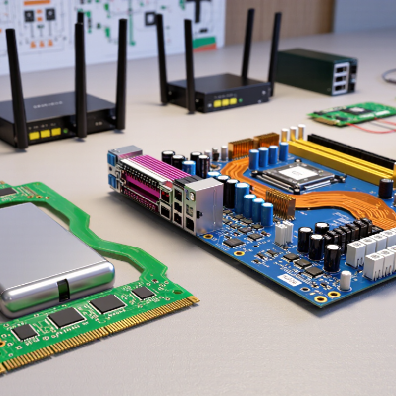
PCB types are commonly classified by layer structure and base material. Single-sided boards place copper on one face, while double-sided boards route connections across both faces. Multilayer boards stack copper layers around an insulating core, allowing dense circuits in compact devices. More layers add routing options, but also increase fabrication complexity and inspection needs.
Prismark’s 2024 industry analysis estimated global PCB production value at about US$73.4 billion in 2023, roughly 15% below 2022. This market figure does not identify one winning construction; product requirements drive the choice. FR-4, a glass-fiber epoxy laminate, suits many general-purpose designs. Polyimide supports flexible circuits, while metal-core and ceramic substrates help manage heat in specific applications. Rigid, flexible, and rigid-flex describe board form, not layer count. That distinction is easy to miss. A rigid-flex board, for example, combines bendable sections with rigid areas for mounted components.
Tips: Match the material to temperature, bending, and electrical needs. Check the finished stack-up with your fabricator, especially for controlled impedance or tight bend zones. A simple classification chart can mislead; confirm the actual construction before comparing quotes.
Single-Sided, Double-Sided, and Multilayer PCB Designs
Single-sided PCBs carry copper traces on one face, making them simple to lay out and economical for basic controls, indicator panels, and low-density circuits. Their limited routing space can force wider boards or awkward component placement. Small boards. Tight limits. For a compact sensor, a few crossing signal paths may already make a single-sided design impractical.
Double-sided boards use copper on both faces, connected through plated holes. This gives designers more routing options without the complexity of a multilayer stack. They suit moderate-density controls and consumer electronics, where space and cost both matter. Careful placement still counts: traces routed too close to noisy power sections can weaken signal quality.
Multilayer PCBs sandwich several copper layers inside insulating material, supporting dense layouts and controlled signal paths in computing, communications, and advanced instruments. More layers can save board area, but they raise fabrication and inspection demands. It is tempting to treat layer count as a quality score. It is not. Grand View Research’s Printed Circuit Board Market report estimated the global market at USD 76.2 billion in 2023 and projected 5.6% annual growth from 2024 to 2030. That growth spans many board types; it does not mean every design needs more layers. Choose based on routing density, electrical needs, size, and production cost. The right choice is sometimes less obvious than a layer count suggests.
What Are the Top Types of PCB Printed Circuit Boards? — Single-Sided, Double-Sided, and Multilayer PCB Designs
Rigid, Flexible, and Rigid-Flex Circuit Boards
Rigid, flexible, and rigid-flex boards solve different packaging problems. Rigid boards use a stable laminate, often fiberglass-reinforced epoxy, and suit fixed layouts in control units or appliances. They support dense multilayer routing and are usually easier to fixture and inspect. Flexible boards use thin polymer films, allowing circuits to fold around a camera module or fit inside a narrow wearable. They can reduce cables and connectors. However, repeated movement needs careful bend-radius and copper-pattern design. Rigid-flex combines solid sections with flexible connections. It can reduce assembly steps, but fabrication and repair are more demanding.
The market remains substantial: Prismark’s 2023 industry forecast projected global PCB production value would rebound about 5% in 2024, to roughly $71.8 billion. That figure covers PCB production overall, not just one board type. It signals a broad, active supply chain, but does not tell designers which construction is best. There is no universal winner. Rigid-flex may save space and connectors, yet its added process complexity can outweigh those benefits in a simple, stationary product.
Tips: Mark the bend zone before routing a flex section. Check the supplier’s minimum bend radius, copper type, and layer stack early. For a prototype, confirm whether the flex will bend once during installation or move repeatedly in service. Those are different design conditions. Small details matter.
(Prismark, 2023 PCB industry forecast)
Specialized PCBs: HDI, Metal-Core, and Ceramic Types
Specialized printed circuit boards address design limits that standard boards may not handle well. High-density interconnect (HDI) boards use fine traces, small pads, and microvias to fit more connections into a compact area. They suit tightly packed devices, such as small sensors or handheld electronics. Yet finer geometry leaves less room for manufacturing variation. A layout that looks efficient on screen may need careful review for assembly and testing.
Metal-core PCBs typically place a conductive metal base beneath an electrically insulating dielectric layer. This structure helps move heat away from components, such as power LEDs, but it does not replace proper thermal design. Check the heat path, mounting method, and dielectric properties together. Ceramic PCBs can offer strong thermal performance and stable dimensions in demanding conditions. They can also be brittle and costly. The trade-off is easy to underestimate; I would not choose a type from one specification alone.
Tips: Match the board to the actual constraint: routing density, heat, or stability. Ask the fabricator about minimum features and tolerances, then review the design with those limits in mind. Small details matter. A thermal test or prototype can reveal assumptions that drawings miss.